Below are some images showing an historic building in Montreal Canada having insulation added, and about to be re-clad with new brick.
Most of the historic buildings, including the triplexes of Montreal, are built with this 'piece sur piece' massive wood construction technique with wood members that can be two or three inches by ten or twelve inches (3" x 12"). The wood was stacked piece on piece and notched together to form the structure for the building which was followed by tar paper and one layer of brick masonry cladding. Ultimately it is a refined version of a log cabin, with bricks slapped on top to prevent the whole city from burning down if there was a fire, and it worked well. The bricks were "attached" to the wood structure by nails laid into the mortar as the masonry work proceeded, the earliest version of the modern day "brick tie'.
These buildings are not solid structural brick or stone, but there is, however, usually a shared masonry 'mur mitoyen' (party wall/fire wall) that is the separating wall between buildings and provides good fire separation. It is common today to see these shared walls as 'exposed brick' inside many of the buildings, but it is clear that they were never meant to be seen, because many of the bricks are mis-matched and random colours and shapes (clinker bricks) with tons of mortar squishing out everywhere, they are sort of a joy to look at! I believe they are typically 6 rows thick of brick masonry, I'll try to get some photos of one of these walls for another post.
In present day when buildings that have been neglected for decades are finally repaired, they often remove all of the exterior brick, place a thin layer of insulation on top of the structural wood, followed by a air barrier, then re-clad with new bricks. This is what you see in the photos below. The thickness of the foundation wall usually determines how thick the insulation can be, as it was usually built directly along the property line and too much insulation will cause the new wall construction to cross the property line, so there are limits. In most cases almost all the character and detail of the historic brick and patterns are lost when replaced with new uniform modular bricks. By contrast, if there are no structural issues, the interior of walls - which are usually a layer of lathe applied to the inside surface of the wood structure, followed by a layer of (sometimes elaborate) finishing plaster - can be maintained.
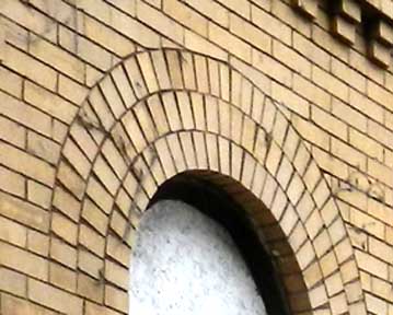
You can also see an-infilled window in the photos, which tells that the building was modified at some point. My guess is that the original entrance was at the corner, but it was later changed when it was separated into different apartments with three doors added at the side. Its hard to say without seeing the interior. This is not a typical triplex (see two blog posts prior for triplex information), it just has the same construction technique.


Most of the historic buildings, including the triplexes of Montreal, are built with this 'piece sur piece' massive wood construction technique with wood members that can be two or three inches by ten or twelve inches (3" x 12"). The wood was stacked piece on piece and notched together to form the structure for the building which was followed by tar paper and one layer of brick masonry cladding. Ultimately it is a refined version of a log cabin, with bricks slapped on top to prevent the whole city from burning down if there was a fire, and it worked well. The bricks were "attached" to the wood structure by nails laid into the mortar as the masonry work proceeded, the earliest version of the modern day "brick tie'.
These buildings are not solid structural brick or stone, but there is, however, usually a shared masonry 'mur mitoyen' (party wall/fire wall) that is the separating wall between buildings and provides good fire separation. It is common today to see these shared walls as 'exposed brick' inside many of the buildings, but it is clear that they were never meant to be seen, because many of the bricks are mis-matched and random colours and shapes (clinker bricks) with tons of mortar squishing out everywhere, they are sort of a joy to look at! I believe they are typically 6 rows thick of brick masonry, I'll try to get some photos of one of these walls for another post.
In present day when buildings that have been neglected for decades are finally repaired, they often remove all of the exterior brick, place a thin layer of insulation on top of the structural wood, followed by a air barrier, then re-clad with new bricks. This is what you see in the photos below. The thickness of the foundation wall usually determines how thick the insulation can be, as it was usually built directly along the property line and too much insulation will cause the new wall construction to cross the property line, so there are limits. In most cases almost all the character and detail of the historic brick and patterns are lost when replaced with new uniform modular bricks. By contrast, if there are no structural issues, the interior of walls - which are usually a layer of lathe applied to the inside surface of the wood structure, followed by a layer of (sometimes elaborate) finishing plaster - can be maintained.
You can also see an-infilled window in the photos, which tells that the building was modified at some point. My guess is that the original entrance was at the corner, but it was later changed when it was separated into different apartments with three doors added at the side. Its hard to say without seeing the interior. This is not a typical triplex (see two blog posts prior for triplex information), it just has the same construction technique.